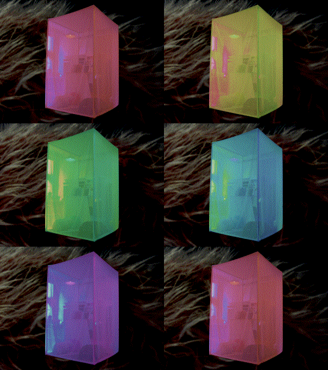
I developed the ideas from the second lab into a multi-media installation: Room of all Colors and Sounds.
Project Discription: https://itp.nyu.edu/projects/projectinfo.php?project_id=3213
The project was accomplished by building 3 capacitive sensors described in the section 2 lab. The max patch and arduino code were modified in order to accommodate for more sensors. A building a simple DMX shield enabled me to control DMX lights in addition to sound and video. Looking at schematics of a different DMX shield enabled me to know that the illegibly-label resistor is a 100 Ohm resistor. The code for the arduino was a little tricky as well as I had to figure out how to communicate with pins directly because that is a lot faster and the capacitive sensor depend on calculations that happen in extremely short time intervals. The code is below:
#include <DmxSimple.h>
int i;
unsigned int x, x1, x2, y, y1, y2;
float accum, fout, fout1, fout2, fval = 1.0; // these are variables for a simple low-pass (smoothing) filter – fval of 1 = no filter – .001 = max filter
int flag = 0;
int value = 0;
int channel;
void setup() {
Serial.begin(9600);
DDRB=B10101;
//DDRD = DDRD | B10000000
//DDRD &= B1011111
pinMode(7, OUTPUT);
pinMode(6, INPUT);
pinMode(5, OUTPUT);
digitalWrite(5, LOW);
// DDR is the pin direction register – governs inputs and outputs- 1′s are outputs
// Arduino pin 8 output, pin 9 input, pin 10 output for “guard pin”
// preceding line is equivalent to three lines below
// pinMode(8, OUTPUT); // output pin
// pinMode(9, INPUT); // input pin
// pinMode(10, OUTPUT); // guard pin
digitalWrite(10, LOW); //could also be HIGH – don’t use this pin for changing output though
}
void loop() {
y = 0; // clear out variables
x = 0;
x1 = 0;
x2 = 0;
y2 = 0;
y1 = 0;
for (i=0; i < 4 ; i++ ){ // do it four times to build up an average – not really neccessary but takes out some jitter
// LOW-to-HIGH transition
PORTB = PORTB | B00001; // Same as line below - shows programmer chops but doesn’t really buy any more speed
// digitalWrite(8, HIGH);
// output pin is PortB0 (Arduino 8), sensor pin is PortB1 (Arduinio 9)
while ((PINB & B0010) != B0010 ) { // while the sense pin is not high
// while (digitalRead(9) != 1) { // same as above port manipulation above – only 20 times slower!
x++;
}
delay(1);
PORTB &= B11110;
while((PINB & B0010) != 0 ){ // while pin is not low — same as below only 20 times faster
// while(digitalRead(9) != 0 ) { // same as above port manipulation – only 20 times slower!
y++;
}
delay(1);
PORTB = PORTB | B10000;
while ((PINB & B1000) != B1000 ) { // while the sense pin is not high
// while (digitalRead(11) != 1) { // same as above port manipulation above – only 20 times slower!
x1++;
}
delay(1);
// HIGH-to-LOW transition
//PORTB = PORTB & 0xFE; // Same as line below – these shows programmer chops but doesn’t really buy any more speed
//PORTB = PORTB | 00000;
PORTB &= B01111;
while((PINB & B1000) != 0 ){ // while pin is not low — same as below only 20 times faster
// while(digitalRead(11) != 0 ) { // same as above port manipulation – only 20 times slower!
y1++;
}
delay(1);
PORTD = PORTD | B10000000;
while ((PIND & B01000000) != B01000000 ) { // while the sense pin is not high
// while (digitalRead(11) != 1) { // same as above port manipulation above – only 20 times slower!
x2++;
}
delay(1);
// HIGH-to-LOW transition
//PORTB = PORTB & 0xFE; // Same as line below – these shows programmer chops but doesn’t really buy any more speed
//PORTB = PORTB | 00000;
PORTD &= B01111111;
while((PIND & B01000000) != 0 ){ // while pin is not low — same as below only 20 times faster
// while(digitalRead(11) != 0 ) { // same as above port manipulation – only 20 times slower!
y2++;
}
delay(1);
}
//fout = (fval * (float)x) + ((1-fval) * accum); // Easy smoothing filter “fval” determines amount of new data in fout
//accum = fout;
fout= (float)x+float(y);
fout1=(float)x1+float(y1);
fout2=(float)x2+float(y2);
// Serial.print((long)x, DEC); // raw data – Low to High
// Serial.print( “ “);
Serial.print((long)fout, DEC); // raw data – High to Low
Serial.print( “ “);
Serial.print((long)fout1, DEC); // raw data – High to Low
Serial.print( “ “);
Serial.println((long)fout2, DEC); // Smoothed Low to High
//Serial.println((long)x, BYTE);
delay(10);
int c;
while(Serial.available() > 0){
c = Serial.read();
if (c != ‘ ‘){
if ((c>=’0′) && (c<=’9′)) {
value = 10*value + c – ’0′;
} else {
if (c==’c') channel = value;
else if (c==’w') {
DmxSimple.write(channel, value);
//Serial.println();
}
value = 0;
}
}
}
}
